- COMPOUNDING

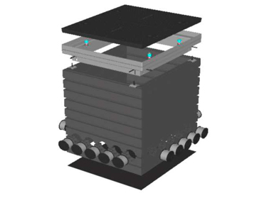
The basic kit consists on:
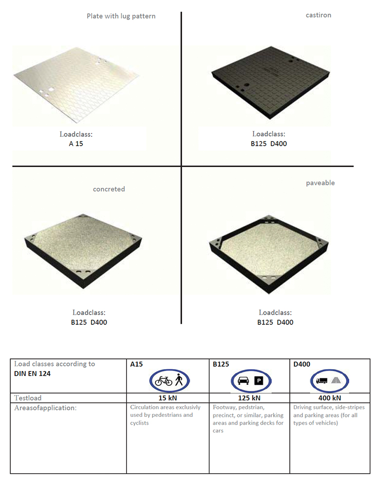
1) an individual manhole cover, Plate with lug pattern, Cast iron, Concreted steel tub, Paveable steel tub
2) 2 a hot-dip galvanized steel frame (with a 5 mm high elastomer insert) fiberglass reinforced polycarbonate frame, a height adjustment (max. 50 mm) and all needed screw joints included
3) Standard bore holes (see illustrations of the Individual manholes in the price list) with steel reinforced vario entering guides (40-162 mm)
4) a baseplate with fiberglass reinforced polycarbonate frame
Adjustable manhole height:
By choosing an individual number of prefabricated polycarbonate frames (fibre-glass reinforced) it is possible to deliver the manhole in customer-friendly height
The increase oft he height by one polycarbonat frame is 103,50 mm
- CABLE MANHOLE COVERS AND LOAD CLASSES
- ASSEMBLY INSTRUCTION
Assembly Instruction BE-KS
Installation of the cable duct
The civil engineering company must properly assess the soil conditions and construct an excavation pit for the respective size of the Boston Europe cable ducts. This can be, for example, a compacted, 10 cm thick base of mixture of gravel and sand or of concrete B 10.
The duct can now be constructed from the individual components on this excavation base.
CAUTION! Please do not install damaged parts. (If ducts or duct parts arrive damaged, please photograph, and send them to Boston Europe as soon as possible.)
When used in roadways, the duct should not be installed directly into the lane. (For reasons of noise generation).
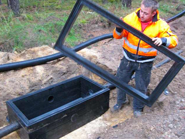
1) Baseplate positioning
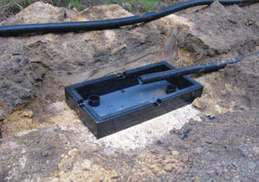
Excavation of the building pit according to the requirementsalternatively to the arrangement of the bore holes and flattenwith an air level.
Put the baseplate (with the fibre-glass reinforced polycarbonate frame) horizontally on the ground or into the building pit andangle the baseplate with an air level.
2) Height determination of the tube or the cable inlets
After the horizontal justification of the base plate the vertical positioning of the tube or cable inletscan be made.By choosing an individual number of polycarbonate frames between the double frame (with thebore holes) and the base plate, it is possible to set the tube or cable inlets in customerfriendlyheight. The increase of the height by one polycarbonatframe is 103,50 mm.

3) Tube- / cable inlets
The vario standard entering guides will be sliced to the desiredtube diameter with the help of prefabricated tube outlets.
By superstructure or laying the manhole on existing cables orcable protection tubes, the cable or pipe ends will be equippedwith a vario standard entering guide and placed into the lowestpolycarbonate frame (with the bore holes).
Before the bore holes will be closed with the upper polycarbonate frame, it has to be ensured that there is no dirtbetween the frames.
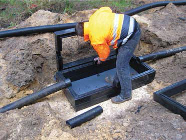
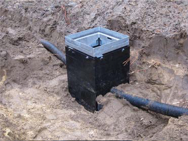
4) Build up cable manhole height
After insertion of the cable or cable protection tubes, the assembling of the complete manhole height can be occur.
The polycarbonat frames will be piled after another till the desi red height is reached.
Possible dirt between the frames shoud be removed.
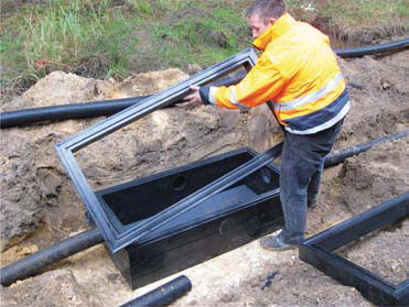
5) Put on the steel frame

The last level presents the steel frame incl. top frame (made offiber glass reinforced polycarbonate).
With help of the integrated height adjustment an infinitely variable height and gradient compensation is possible (max. 50 mm).
6 mm hexagonal socket wrench or a universal installationwrench required.
6) Insert and lock the cover

The insertion of the manhole cover can be done with a coverlifter or the a installation wrench.
The space between the steel frame and the polycarbonat frame has to be caulked with cement mortar (quality > C12/15).
After the insertion of the manhole cover the cable manhole hasto be filled and compressed in layers.
7) Workflow

Normally the ducts arrive fully packed on EU pallets.
Place the ground plate, i.e. the lowest polycarbonate frame on the sole. (A 5 mm thick plastic base is already screwed to a single frame)
On demand the cable protection tubes can also be installed beforehand.

Place the frames on the ground plate in the received order. If you want to stick the single frames together, do not apply the glue (will be sent by us on request) too thickly. Lightly apply a thin layer of the glue to the entire top of each frame with a commercially available brush and place the next frame on top.
Place all polycarbonate frames one on top of each other until the desired height is reached.
The last step is to install the head frame. This consists of a single frame made of PC that is bolted to a steel frame. Any necessary level adjustment can be made by means of the height compensation.

If you want to activate the height compensation:
Gradually fill the excavation pit with compactable material and compact it mechanically with suitable equipment before activating the height compensation. Only after compaction can the height compensation be set, and the joint can be filled with mortar.
Please note the information provided by the mortar manufacturer!
Boston Europe cable ducts may only be loaded when the used mortar has reached the strength specified by the mortar manufacturer.

Height Compensation!
After the duct has been placed in the excavation pit, which has been backfilled and compacted, the height compensation can be activated:
To activate the height compensation, the 4 nuts on the sides must first be loosened! The steel frame is adjusted to the ground level with the supplied tool using the threaded rods or set to the height intended for the duct cover.
Please make sure that all threaded rods really stand on the sheet metal base! Once the adjustment has been made, the steel frame is lifted off and placed next to the duct.
The resulting free space is filled with dry mortar in accordance with DIN 18555 (compression strength> 35 N / mm² after 28 days).
The supplier is e.g. the company Ergelit in Alsfeld.
Dry mortar: e.g. type Kombina 35 S or alternatively "paving mortar" Immediately after filling the joint, the upper frame is returned to the position intended for it.
The threaded rods push through the still soft dry mortar until they are back on the sheet metal base.
Last you can insert and lock the cover. Each cover is equipped with two locks.
Pipe Inlet:
The adapters can be cut to the desired size using a commercially available box cutter or something similar. The markings on the adapters are intended for standard pipes. (Please discuss special pipe sizes in advance)